The Inner Product, March 2003
Jonathan Blow (jon@number-none.com)
Last updated 16 January 2004
Unified Rendering Level-of-Detail, Part 1
Related articles:
Rendering
Level-of-Detail Forecast
(August 2002)
Unified Rendering LOD, Part 2
(April 2003)
Unified Rendering LOD, Part 3
(May 2003)
Unified Rendering LOD, Part 4
(June 2003)
Unified Rendering LOD, Part 5
(July 2003)
Last year, in the article "Rendering Level-of-Detail Forecast" (August
2002), I discussed a few of the most popular methods of LOD management. I
opined that most LOD schemes are too complicated for the benefit they provide,
and I gave a high-level overview of the method I would choose to implement LOD
management over large, generalized scenes.
Now, I'm going to put my money where my mouth is, and implement such a scheme.
It's a big project; the resulting source code will be the biggest this column
has seen, by far.
Goals of the System
We would like the system to reduce the number of triangles used to render
distant objects, where precise detail is not necessary. Some algorithms, like
the Lindstrom-Koller and ROAM descendants, do this by modifying the world mesh
at a granularity of individual triangles. These algorithms are unacceptably slow
at high detail levels. Also, many of these systems try to utilize frame
coherence, which makes them unsuitable for interactive systems. (This may sound
like a controversial statement because frame coherence is a standard tool in the
graphics guy's optimization toolbox; but that is mainly because the culture of
graphics optimization has its origin in tools for batch rendering, for film and
similar applications. In games, we unquestioningly accepted frame coherence
exploitation as a good thing; but it inherently produces unstable frame rates,
and frame rate stability is a major priority for smooth interactivity. Look for
an explanation of this, and a corresponding rant, in a future column.)
So, we want the system to operate at a large granularity, raising or lowering
the detail of big chunks of geometry all at once. Thatcher Ulrich's
appropriately-named "Chunked LOD" system works like this, and it runs very
quickly. However, it uses the "binary triangle tree" tessellation, the same one
that ROAM uses. This tessellation is very inefficient about how it allocates its
triangles (though you won't find a serious efficiency analysis in any research
paper promoting binary triangle trees!). Also, it means that regular-grid height
fields are the only kind of geometry on which the algorithm can be easily used.
With a lot of work, the algorithm can be extended to other topologies. But the
amount of work necessary is large, it complicates the runtime system
tremendously, and the system still won't handle arbitrary input meshes.
Thatcher chose the BTT topology to make it easy to fill the cracks between
neighboring chunks of terrain. This is important because cracks look awful. We
want to fill cracks correctly, and quickly, but without restricting the mesh
topologies. Arbitrary mesh topology is important because we want to create a
method of _unified_ LOD management, which can be used for expansive outdoor
terrains, or small enclosed dungeons, or for animated characters.
Aside from topology, we want the system to place a minimal number of other
constraints on mesh storage and rendering. An example of such constraints is
seen with progressive meshes. It is a complicated and somewhat inefficient task
to render a progressive mesh as a series of triangle strips; it is nigh
impossible to render it as a series of vertex-cache-optimized triangle strips.
If we introduce too many constraints, then when we come along to add new
features to our engine, like stencil shadows or normal-mapping geometry
enhancement, we may find that constraints of the new features clash with the old
LOD constraints. This forces us to eliminate the new feature, or to dump our LOD
system and make a new one. Either outcome is bad.
Finally, we want the system not to exhibit popping from one LOD to another.
Popping looks ugly and is distracting to players; often we are looking for
movement in our surroundings, and LOD popping creates false movement. Because we
are choosing to adjust detail at a large mesh granularity, we will naturally get
a lot of popping unless we spend significant effort to avoid it.
To summarize, I'll list all the main goals now as bullet points:
Reducing the detail of distant geometry
My overall approach will be to cut the world geometry into pieces at preprocess
time, and generate several detail levels for each piece. At runtime, I will
choose an appropriate detail level for each piece and then render it, filling in
the cracks.
To generate the various levels of detail, I will use Garland-Heckbert Error
Quadric Simplification, or "EQS" (see For More Information). The input to EQS is
a mesh of arbitrary topology, and it produces a mesh of arbitrary topology. We
like that since it doesn't restrict us.
When reducing the mesh, I use what Garland and Heckbert call "subset placement":
I pick a vertex, then drag it to the position of a nearby vertex, then remove
all the triangles that have become degenerate. The alternative is "optimal
placement", where you solve for the position of a new vertex, then move two
vertices into that new position. Subset placement is easier to program than
optimal placement, but it probably produces a lower-quality output
triangulation. Nevertheless, I chose subset placement because of its extreme
generality. The output vertices are a subset of the input vertices, which means
that they comprise valid and undistorted mesh data. With optimal placement, you
must interpolate and extrapolate to produce the values for each vertex (not just
position, but texture coordinates, perhaps tangent frames, bone blending weights
for animated meshes, or other arbitrary vertex-associated data). Linear
interpolation might not be good enough, or might require specialized
renormalization; extrapolated values might need to be bounded in
application-specific ways. It is definitely possible to do these things, but
there's still no guarantee that the machine-generated coordinates will look
good. It costs a lot of extra work and software complexity, to gain a
potentially small visual benefit. Also, since the work is highly dependant on
the type of data stored at each vertex, it's difficult to make a generalized
tool that operates in a "hands-off" manner.
To be clinical: the choice to use optimal placement creates extra dependencies
between the mesh simplification tool and the data format. Since dependencies are
the bane of software engineering and project management, it is best to use
subset placement in almost all cases.
Dividing the geometry into pieces
For now, in order to make it easy to divide the world into blocks, and to
simplify other tasks like crack-filling, we'll limit ourselves to rendering
height fields. By the end of this series, though, we'll be operating on triangle
soups. There's a fine line to walk here -- I want to make the system simple
enough that I can progress quickly programming it, so I start with just height
fields; but at the same time, I don't want this to be a permanent restriction,
so I must be careful not to rely on techniques that cannot be extended beyond
height fields. In other words, for every simplification I impose now, I need to
have a believable story about how that piece of the system will be upgraded in
the future. It's a sort of algorithmic bootstrapping, if you will.
With a height field, it's easy to divide the world: you have some big array of
height samples for the entire world, and you copy out rectangular subsections of
that array. Because the array is evenly-sampled, we can easily match up the
vertices along the edges of the blocks, which is necessary for crack-filling
(discussed later). Note that there is no limit on the size or aspect ratio of
these subsections; you can choose them arbitrarily based on your needs. This
contrasts starkly with the binary triangle tree algorithms, which want your
blocks to be square and power-of-two-plus-one in size, which is often
inconvenient.
In a future upgrade, to handle unrestricted input meshes that extend arbitrarily
into all three dimensions, I'll clip the meshes against axis-aligned planes to
divide them into a bunch of cube-shaped regions. When clipping triangles against
planes, we create all the new vertices ourselves, and in fact we create them in
pairs. By saving the information about which vertices correspond, we will make
it easy to perform crack-filling. But that's a subject for a future article.
Operating at a large granularity
Suppose we choose subsections of the height field that are 21x21 samples. That
gives us 20x20 quads, or 800 triangles per block. Suppose we use mesh
simplification to generate low-res versions of the block at 400 triangles, 200,
100, 50, and 25. Based on the distance from each block to the camera, we choose
one of these detail levels and render it. The result is shown in Figure 1a. It's
bad because most of the rendered blocks consist of a small number of triangles.
Current graphics hardware and drivers do not like that very much; the game will
run slowly.
To solve this problem, we can hierarchically combine terrain blocks before
putting them into the EQS routine to reduce them. Since we're working on a
height field, I chose to combine 4 blocks at a time, prior to simplification. If
the original blocks are 800 triangles each, I combine 4 of them to get a
3200-triangle block; then I simplify tha mesh back down to 800 triangles. Thus
all the rendered blocks have the same number of triangles, regardless of scale,
as you see in Figure 1b. This simplifies some of the math we'll look at later
on.
With fully 3D input geometry, I would be combining 8 blocks into 1, requiring a
more extreme reduction ratio. You may wish to think about the implications.
|
|
| Figure 1a: The squares represent blocks of our world mesh; the numbers denote how many triangles make up each block. If we merely reduce the detail levels of a fixed set of blocks, we will inefficiently render blocks that contain small numbers of triangles. | Figure 1b: By combining blocks, we can eliminate this problem. Note that the total number of triangles in 1b is higher than in 1a; we will worry about this in a future article. |
Filling Cracks
After rendering two blocks, we need to fill the gap between them by rendering an
appropriate set of connecting triangles. I will call this set of triangles a
"seam". Because all of our blocks are precomputed, we can also precompute the
seams. At runtime we only render precomputed arrays, which is very fast.
Most people think of the crack-filling problem in a way that makes it needlessly
difficult. They think about how, when given two arbitrary-LOD blocks, to match
up the vertices along their edges. This is a difficult problem. Fortunately,
though, we don't need to solve it. Instead, we can first build seams between the
highest-LOD blocks. This is trivial; you just iterate along the array and
generate a row of triangles (see Figure 2b). For each vertex of each seam
triangle, you store an integer telling you which block the vertex is connected
to, and another integer telling you the index of the vertex inside that block.
So we're only storing indices, not spatial coordinates. That's important for the
next step.
Suppose we reduce one of the blocks, as in Figure 2c. All we need is for the EQS
routine to tell us which vertex in the source mesh corresponds to each vertex in
the destination mesh. That's especially easy since we used subset placement;
when we collapse a vertex into another vertex, we simply record the index of
where it went. When detail reduction is complete, we return an array that tells
us "For each index in the source mesh, here is the index of the corresponding
vertex in the output mesh". Now we use this array to re-map the indices of the
seam triangles, and we throw away any degenerate triangles. Now we have a valid
precomputed seam for two blocks at differing resolutions. We can repeat this
process as often as we want, reducing either block as much as we want. When we
combine blocks together, we merge their seams. (Seams that end up interior to
the block are tossed in with the block's regular geometry; seams on the borders
are merged together to make bigger seams).
The seams between the highest-resolution blocks, which we generated from the
original height field sampling pattern, are not necessary for rendering. If we
were to render them, all their triangles would be collapsed to 0 area; Figure 2
is drawn with the blocks artifically pulled apart to make the filling pattern
clear. So we throw those seams away after the preprocess, keeping only the seams
that involve detail-reduced blocks.
 |
|
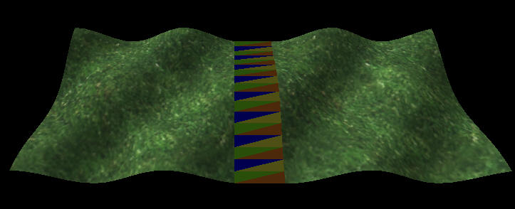
| Figure 2a: Two blocks of terrain, connected by a seam. The blocks are drawn with an exaggerated gap between them; in actual game rendering, they would be touching. The seam is drawn with intentionally strange coloring to show the individual triangles. | |
 |
 |
| Figure 2b: A wireframe version of 2a. | Figure 2c: The right-hand block has been reduced to 1/4th its original triangle count. The seam is created by cross-referencing the seam of 2b through an index map provided by the mesh simplifier. |
Now the question arises: how many of these seams do we need to precompute, and
how do we organize them in memory? Clearly we need an appropriate seam between a
given block and any of its possible neighbors. To reduce the number of
possibilities, I decided to place a restriction on the LODs of rendered blocks:
two neighboring blocks are not allowed to differ by more than one level of
detail. So for any given block, all his neighbors will either be the same size,
one-half his size (measuring just the length of an edge, not area), or double
his size.
If every block stored all the seams for all its neighbors, we'd be storing every
seam twice: both block A and block B would store the seam that attaches A to B.
Instead, I store only seams for neighbors in the +X and +Y directions.
In the end, each block has eight seam pointers. There are 4 for the +X direction
and 4 for the +Y. The four pointers are: seam to lower-resolution block, seam to
same-resolution block, and two seams to the two higher-resolution neighbor
blocks.
After all this seam-filling, there will still be some small holes in the
terrain, where the corners of blocks meet, as seen in Figure 3. For the case of
a height map, these can be filled very quickly at runtime. I won't explain the
details now, since the procedure will change significantly when we adapt the
algorithm to generalized meshes.
 |
| Figure 3: Three terrain blocks (gray with black borders) and the seam fills between them (red with dotted borders). Note the hole in the middle. These blocks are drawn with exaggerated gaps; the actual hole would be very small. |
Sample Code
This month's sample code renders a height field with filled seams. It also does
some work to eliminate popping. Next month we'll discuss popping in detail, and
look at methods of choosing which LOD to use for a given block.