αred + αgreen = 1
The Inner Product, April 2003
Jonathan Blow (jon@number-none.com)
Last updated 16 January 2004
Unified Rendering Level-of-Detail, Part 2
Related articles:
Rendering
Level-of-Detail Forecast
(August 2002)
Unified Rendering LOD, Part 1
(March 2003)
Unified Rendering LOD, Part 3
(May 2003)
Unified Rendering LOD, Part 4 (June 2003)
Unified Rendering LOD, Part 5
(July 2003)
Last month I started building a unified LOD system. The intention is to create a
generalized method of LOD management that works for environments, objects, and
characters. LOD systems tend to be complicated, and complicated systems hamper
the game development process. For example, they can impose difficult constraints
on mesh topology or representation. To prevent such impediments, we want to make
the LOD system as simple as possible.
I chose static mesh switching as the underlying LOD method. Last month I
discussed the basic technique of generating blocks at various levels of detail,
and building seams between the blocks to prevent holes from appearing in the
world. But this technique alone is insufficient; switching between static meshes
will cause visible popping in the rendered image, so I need to address that
somehow.
Preventing Popping
There are three methods that are often used to prevent popping. The first method
I will call "incremental transitioning"; the idea is to pop only small subsets
of a mesh each frame, in the hope that the small pops will be nearly invisible.
Continuous LOD and progressive mesh systems employ this idea. However, one of
the core decisions of my algorithm is that, for maximum simplicity, all meshes
are treated as atomic units. Thus every triangle in a mesh is in the same LOD
state as every other; incremental transitioning is not possible here.
The second method is geomorphing, in which we move the vertices slowly from
their positions in the low-res shape to their positions in the high-res shape
(or vice versa). The third method is color blending; we draw the block at both
levels of detail and interpolate between the resulting colors.
I had to decide between geomorphing and color blending, and I chose color
blending. First I'll talk about the basic implementation of the color blending
technique; then I'll spend some time justifying my decision. Justification is
necessary because color blending might at first glance seem wacky and
inefficient.
Color Blending: The basic idea
With color blending, we want to transition between LODs by rendering each LOD
individually, then blending the output colors at each pixel. On DirectX 8-class
hardware and earlier, we would do this using alpha blending to crossfade between
the meshes, while doing some tricks to ensure that reasonable values end up in
the Z buffer.
Given DirectX 9 or above, with multiple render targets, color blending becomes
easy. So I'll concentrate on the trickeir implementation with DirectX 8 and
earlier.
The basic method I use for the blending was recently reintroduced to me by
Markus Giegl (see the References), though I swear I saw it a while back in some
publication like the ACM Transactions on Graphics. We could imagine naively
cross-fading between the two LODs; this would involve drawing one LOD with an
alpha value of t, and the other with alpha 1-t (Figure 1a). Neither mesh would
be completely opaque, so we'd be able to see through the object to the
background. That's just not workable.
Giegl proposes altering the cross-fading function so that one of the meshes is
always opaque (Figure 1b). We fade one mesh in, and only once it becomes
completely solid do we begin to fade the other mesh out.
|
|
| Figure 1a: A typical cross-fading function; for all
t, αred + αgreen = 1 |
Figure1b: A modified cross-fade; for all t, at least one of the functions has α = 1. |
I do things differently than Giegl proposes in his paper. When drawing the
translucent mesh for any particular block, I found that if I left the Z-buffer
writes turned off, unpleasant rendering artifacts would occur, since distant
portions of the translucent mesh often overwrote nearby portions. This could be
solved by sorting the triangles in the translucent mesh by distance, but that's
very slow. Instead, I render the transparent mesh with Z-buffer writes enabled.
Technically this is still not correct, since self-occluded portions of the
translucent mesh may or may not be drawn, but at least the results are
consistent from frame to frame. On the whole, it looks reasonable. Giegl's paper
suggests disabling Z-writes for the translucent meshes, which I cannot believe
produces good results for nontrivial scenes.
It's important that I render the translucent mesh after the opaque mesh;
otherwise the Z-fill from the transparent mesh would prevent portions of the
opaque mesh from being rendered, creating big holes. This rendering order
creates an interesting problem. When the blend function in Figure 1b switches
which mesh is opaque, I need to change the order in which the meshes are drawn.
At first A is transparent and B is opaque, so I draw B first, then A. Then A
becomes opaque, so I draw A first, then B. Interestingly, no consistent depth
test function can be used to prevent popping. Consider the pixels of A and B
that have the same Z values; that is, the quantized intersection of A and B.
If we render the meshes with Z-accept set to <=, then these intersection pixels
will be filled by A immediately before the switch, and filled by B immediately
after the switch, causing a pop. If the Z-accept is <, then the pixels where Z
is equal will show as B before the switch, and A afterward. To circumvent this
problem, I switch the Z function when I switch the mesh rendering order. Before
the switch-over, I render with Z-accept on <=; after the switch-over, I render
with Z-accept on <. Thus the intersection pixels are always filled by A.
We will still have some Z-fighting after we have done all this, because we are
rendering a lot of intersecting geometry. But in general the Z-fighting doesn't
look too bad, since the different LODs tend to be similar. On higher-end
hardware, we can increase the precision of the Z-buffer to mitigate this
problem.
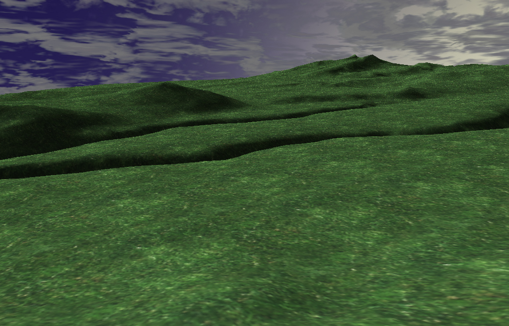
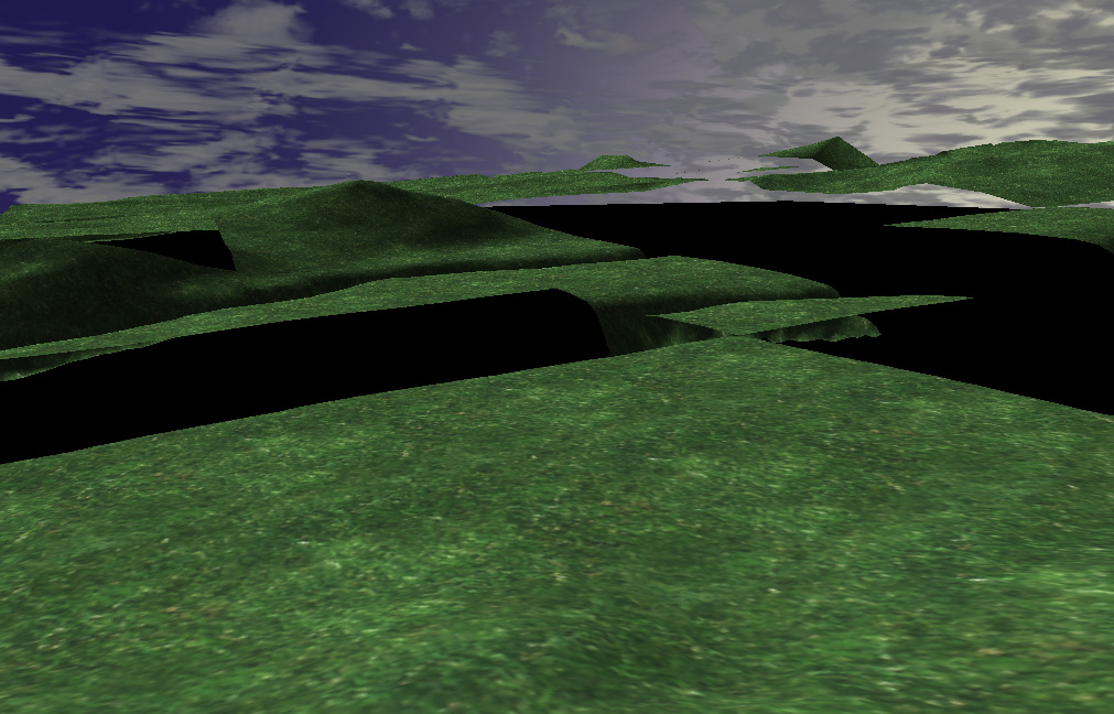
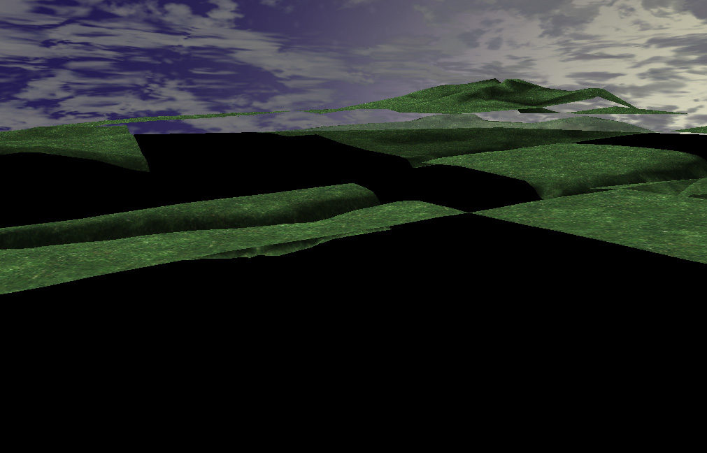
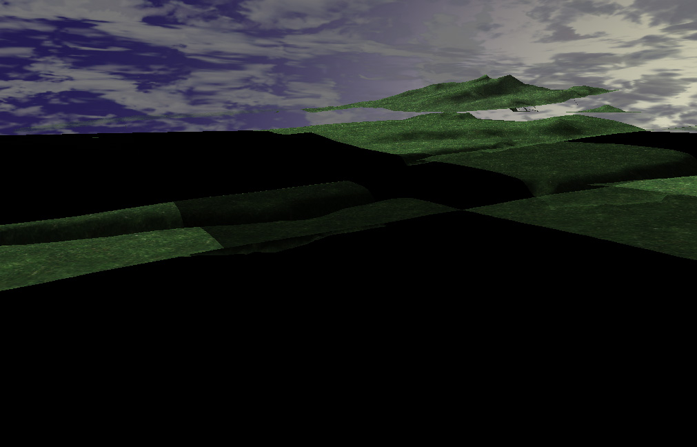
A terrain scene like Figure 2a will contain some blocks that are transitioning
between LODs, and some that are not. First, I render non-transitioning blocks as
completely solid; these are very fast since we're just doing vanilla static mesh
rendering (Figure 2b). Other blocks are either "fading in" (Figure 2c) or
"fading out" (Figure 2d); each of these types of blocks is rendered
translucently, after the corresponding opaque mesh is drawn.
 |
 |
| Figure 2a | Figure 2b |
 |
 |
| Figure 2c | Figure 2d |
If we're not careful about rendering order, we will have problems where we
render a translucent block, then a solid block behind it, causing pixels in the
solid block to Z-fail. To prevent this we can render all the solid blocks first,
then render the translucent blocks back-to-front.
You might think that color blending would be much slower than geomorphing, since
we are rendering more triangles for transitioning objects, and rendering twice
as many pixels. But as we'll see below, the vertex and pixel shaders for color
blending are simpler and faster. As it turns out, the cost for geomorphing can
approach the cost of rendering geometry twice.
Geomorphing: The basic idea
The most straightforward way to perform geomorphing is to interpolate the vertex
positions each frame on the main CPU, then send the resulting triangles to the
graphics hardware. This results in slow rendering; to render quickly, we want
all the geometry to be resident on the GPU.
With modern vertex shaders as of DirectX 9, we can interpolate the geometry
directly on the hardware. To do this we must store position data for both LODs
in the data for each vertex, because vertex shaders provide no way of
associating separate vertices. Then we use a global shader parameter to
interpolate between the positions.
This vertex shader will be longer and slower than a shader that renders a non-geomorphed
mesh. Hopefully, much of the time we are drawing non-geomorphed meshes, and we
only activate geomorphing during the short transition from one LOD to another.
So we will write two vertex shaders, a slow one and a fast one.
That doesn't sound so bad yet, but suppose we want to render animated characters
instead of static meshes. We need a 3rd vertex shader that performs skinning and
such. But now, we also need a 4th vertex shader that performs geomorphing on
meshes that are skinned.
What we're really saying is that we will end up writing twice as many vertex
shaders as we would in the absence of LOD. And don't forget that we need to
maintain those shaders, and handle their interactions with the rest of the
system, throughout the development cycle. That's not nice. Combinatorial
explosion in vertex and pixel shaders is already a big problem, and geomorphing
seems to exacerbate it.
The capability for branching and subroutines is being inroduced into vertex
shaders, and this may help deal with the combinatorial explosions. But it's too
early to say for sure how speed in real games will be affected, and thus whether
the resulting shaders will be useful overall.
Interaction with other rendering techniques
Now we'll look at the problems that can occur when these LOD methods interact
with other parts of the rendering system.
Texture Mapping / Shader LOD
As geometry recedes into the distance, we will eventually want to use
lower-resolution textures for it. If the mesh is made of several materials,
we'll also want to condense those into a single material; otherwise, we will
render only a small number of triangles between each rendering state change, and
that's bad.
In general, at some level of detail we will want to change the mesh's texture
maps and shaders. If we do this abruptly, we'll see obvious popping.
Geomorphing doesn't help us here at all. If we want to smoothly transition
between textures, we need to build some blending logic on top of geomorphing,
making the system more complicated. Since we perform pixel-color logic twice and
blend, our pixel shaders will slow down, perhaps to a speed comparable to the
color blending method. That makes sense, because we're performing a big piece of
the color blending method in addition to geomorphing.
The color blending method by itself, on the other hand, handles texture and
shader LOD automatically. We can use different textures and texture coordinates
and shaders for any of the levels of detail; the LOD system just doesn't care.
It's completely unconstrained.
Normal Mapping
Suppose we are using normal mapping to approximate a high-res mesh with lower-res
meshes. Ideally, we would like to decrease the resolution of our normal maps
proportionally with distance from the camera, just as with texture maps. But
even if we give up that optimization, there's another problem that makes
geomorphing unfriendly to normal mapping.
In general when performing lighting computations, we transform the normal maps
by tangent frames defined at the vertices of the mesh. When geomorphing, we need
to smoothly interpolate these tangent frames along with the vertex coordinates.
Tangent frames exist in a curved space, so interpolating them at high quality is
more expensive than the linear interpolations we use for position. If we quality
of the interpolation is too low, ugliness will occur. So our vertex shader
becomes more expensive -- perhaps more expensive than the color blending method,
which renders 1.25 times the number of triangles that geomorphing does, but with
simpler shaders. (This figure of 1.25 is representative of a heightfield-based
scene; it will change in future articles).
In stark contrast, color blending and normal mapping get along very well
together. The differing LODs can be covered with different normal maps and
parameterized arbitrarily. In fact, we could elect to eliminate normal maps on
the lower LOD entirely.
Stencil Shadows
One nice thing about geomorphing is that stencil-buffer shadows are
implementable without undue difficulty. Because the geometry changes smoothly,
shadow planes extruded from the geometry change smoothly as well. That's an
advantage over color blending.
Suppose we want to use stencil shadows with color blending LOD. The simplest
approach is to choose one of the rendered LODs of each block to generate shadow
volumes. But when the level of detail for a block transitions, its shadows will
change discontinuously. To avoid this, we would like to represent fractional
values in the stencil buffer that we could somehow use to interpolate the
shadows, but the stencil buffer algorithm just doesn't work that way.
I think that for stencil shadows to work with color blending requires DX9-class
hardware or above. We would use two different render targets to generate two
sets of stencil values, one for each level of detail. Then, at each pixel of the
visible scene geometry, we compute a light attenuation factor by interpolating
the results from these two stencil buffers. This technique is nice because it is
highly orthogonal to our mesh representations and shaders.
Since I'm a forward-thinking guy, I consider this to be okay. On a DX8 card,
using this LOD technique, you'd get stencil shadows that pop. But I am designing
this technique to be used in future systems.
Sample Code
In this month's sample code, you can move around a simple terrain that has been
cut into blocks. The color blending method of LOD interpolation has been
implemented to prevent popping.
References
Markus Giegl and Michael Wimmer, "Unpopping: Solving the Image-Space Blend
Problem",
http://www.cg.tuwien.ac.at/research/vr/unpopping/unpopping.pdf