

The Inner Product, May 2003
Jonathan Blow (jon@number-none.com)
Last updated 16 January 2004
Unified Rendering Level-of-Detail, Part 3
Related articles:
Rendering
Level-of-Detail Forecast
(August 2002)
Unified Rendering LOD, Part 1
(March 2003)
Unified Rendering LOD, Part 2
(April 2003)
Unified Rendering LOD, Part 4 (June 2003)
Unified Rendering LOD, Part 5
(July 2003)
My goal so far has been to develop a general method of LOD management that works
for a wide variety of geometry types. But so far I've only discussed the
rendering of regularly sampled height fields. This month I'll start extending
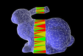
the system to triangle soups. You can see the results in Figure 1.
Recall that the basic algorithm works by dividing the input data into
spatially-localized blocks, then hierarchically combining those blocks. Because
we were working with height fields, the vertices were spread mainly across two
dimensions, so the array of blocks was two-dimensional. Since the input data was
a grid of samples, dividing the data into blocks was easy, and building the
initial seams between high-resolution blocks was also easy.
Now, we want to allow the triangle soup to extend arbitrarily in any direction,
so the array of blocks must be three-dimensional. Building the blocks and seams
will also be more involved. But fortunately, we're already familiar with the
necessary tools; we use them when constructing spatial organizations in a
variety of triangle-processing algorithms.
Clipping or Binning?
We want to divide the input geometry into a three-dimensional grid of blocks.
Since the triangles will not generally be aligned with block boundaries, the
obvious idea is to clip the geometry using planes aligned with the faces of each
block.
However, the goal of dividing the geometry into blocks was just to create groups
of triangles, where each triangle is located near the other triangles in its
group. Strictly speaking, there is no algorithmic requirement that prevents the
blocks' bounding volumes from overlapping. So instead of clipping, we could
divide the geometry as follows: (1) start with a set of empty "bins", each
representing a cubic area of space; (2) for each input triangle, find the cube
that contains its barycenter, and put the triangle into that bin; (3) compute
the smallest axis-aligned bounding volume for each bin by iterating over all the
binned triangles. When you have done this, you'll have a set of rectangular
volumes that are probably a little bigger than the initial cubes, so they
overlap a little bit. Pathologically large triangles might cause the bounding
volumes to overlap significantly, but you can easily subdivide those triangles
to eliminate the problem.
Which of these methods, clipping or binning, should we implement? Clipping
increases the total triangle count, which should be cause for concern. I chose
clipping anyway, though. The reason: even though non-overlapping bounding boxes
were not a basic algorithmic requirement, they provide a greater
interoperability with arbitrary rendering algorithms. Some algorithms require a
strict rendering order for correctness, such as rendering back-to-front. If
we're rendering grid squares that don't overlap, we can quickly achieve correct
ordering of every triangle in the scene like this: (1) sort the triangles in
each block individually; (2) treating each block as an indivisible unit, sort
the blocks by the distance from their center points to the camera; (3) render
the blocks in the sorted order.
This sorting works because the grid squares are regions of space that result
when you chop the space up with a bunch of planes. The applicable idea here is
"render everything on the same side of a plane as the viewpoint, then everything
on the opposite side", which is the same idea that makes BSP tree visibility
work. A grid of cubes is isomorphic to a BSP tree; it's just stored in array
form instead of tree form (and array form has a lot of advantages!)
Now it's true that one of the basic goals of this algorithm is to enable the
treatment of blocks as opaque entities, so that we can run very quickly; if we
need to sort the blocks, we lose much of that speed. But the user of the LOD
algorithm should ideally be free to make that judgement call himself: whether to
adopt an order-dependent rendering algorithm and accept slower running, or
whether to run with unsorted blocks, getting higher triangle throughput, and
using a different shading algorithm. If we don't clip, we make it much harder to
properly sort the scene; we are effectively saying "if you use this LOD
algorithm, you won't be able to do rendering techniques X, Y, or Z without undue
pain".
In fact we saw an order-dependent rendering technique last month: the color
blending method of interpolating between LODs, used on DirectX8 and earlier
hardware. Rather than sorting the triangles in each block, though, the algorithm
used the Z-buffer to effectively sort on a per-pixel level. This color-blending
technique already tolerated some inaccuracy in order to run quickly: occluded
triangles in the translucent layer for a block may or may not contribute color
to the rendered scene, depending on the order the triangles are stored in the
mesh. However, due to the way colors were being blended, the inaccuracies are
small and hard to notice. I suspect that if we used binning, and thus rendered
the scene slightly more out-of-order, the resulting errors would be similarly
subtle, and the result would be acceptable. Just the same, though, one of my
major goals has been to make the system maximally compatible with unforeseen
game engine components. It seems like strict ordering is a potential trouble
spot for cross-algorithm interactions, so I chose clipping.
Then again, maybe the set of conflicting rendering techniques is small and
unimportant. If we decide not to support them, we get a simpler LOD system,
because binning is simpler than clipping. A simpler LOD system is desirable so
that when the user needs to modify it, his job will be easier. Really, this is a
tough call to make.
Another reason I chose clipping in the end was that, with regard to
seam-building, clipping is a superset of binning: you need to solve the weird
cases that happen with binning, and do extra work on top of that to clip. So a
clipping solution illustrates both cases, and if you wanted to simplify the
preprocessing stage to use only binning, you can streamline the sample code
instead of writing something from scratch.
Clipping and Triangle Count
The extra triangles created by clipping may not matter much. When we give the
block to our mesh simplifier -- assuming the simplifier works effectively --
these triangles will mostly be seamlessly merged, so they'll have a small impact
on the resulting triangle count and topology. So the time the extra triangles
should matter most is in the highest-resolution blocks.
On fast modern hardware, when geomtery is finely tessellated, a relatively small
number of triangles are created by clipping. To show why, let's once again look
at a mesh built from a square grid of vertices. The number of triangles in the
block is 2n2, where n is the number of samples on each side of the
block. But the number of triangles added by clipping is approximately 4n. So as
we increase the resolution of our world mesh, the number of triangles added by
clipping grows much more slowly than the number of triangles we actually render.
Building Seams
With seams we follow the same basic strategy presented last month: create seams
between the meshes at the highest resolution, then cross-reference them into the
reduced meshes. This gives us fully precomputed seams that can be rendered
quickly.
For every line segment produced by clipping, we must create a degenerate quad to
bridge any potential gap (Figure 2). Because we're working in 3D now, we have
the possibility that one of these segments will lie on a border between more
than two blocks. If we employ an algorithm that generates seams between blocks
based on which planes the segment touches, we could generate strange spurious
seam triangles in this case.
 |
 |
| Figure 2a: A triangle (brown) has been
clipped by a plane (red dashed line). The resulting convex polygons
must be triangulated, yielding three triangles in this case (green). |
Figure 2b: We insert a degenerate quad (blue) to link the triangles on each half of the plane. The triangles have been artificially pulled apart here so that the quad is visible. |
There are other things we need to worry about, too. When clipping geometry by a
plane, we usually classify vertices as being in the plane's positive halfspace,
or being in the negative halfspace, or lying on the plane. We can end up in a
situation where two connected triangles straddle the plane (Figure 3). Even
though clipping doesn't create new geometry in this case, we need to detect it
and add the appropriate seam.
 |
| Figure 3: Two triangles straddle the clipping plane. |
In the sample code I wanted to solve all this while trying to keep things
simple. The approach I take is to clip each block in isolation, then match up
seams between the blocks after the clipping phase is complete. Whenever I create
a new edge via clipping, or detect an edge coplanar to one of the clipping
planes, I add it to a list of potential seam edges. When all the blocks are
clipped, I look at neighboring blocks and match up edges, creating degenerate
seam quads between them. This two-pass approach is also important for out of
core clipping, which may be necessary for large input geometry; so it's good to
have it already built into the core algorithm.
When matching up the seam edges between blocks, we need to ensure that we don't
attach the wrong edges to each other. There might be ambiguity due to multiple
vertices located in the same positions, or due to floating-point calculations
coming out slightly differently when edges are clipped multiple times. (Ideally
such floating-point problems don't happen if you're careful in the code that
computes clipped coordinates; but the current state of FPU management in Windows
game software is dicey so extra care is warranted.) To eliminate all ambiguity,
I identify each edge by its two endpoint vertices; each of those vertices is
identified by three integers: the two indices of the vertices in the input mesh
that comprised the segment that was clipped to yield this vertex, and the index
of the clipping plane that clipped that segment. If the preceding sentence is
difficult to decipher, the details aren't so important; the basic idea is that
we have a unique integer method of identifying each clipped edge, and we don't
rely at all on the floating-point output of the clipping system to match them
up.
Remember last month we saw that, in the heightfield case, holes will appear in
the mesh between the corners of blocks at varying LODs. An analogous problem
happens in 3D, and we need to analyze that. Also, we haven't discussed methods
of deciding which LOD of a given block to render. We'll get to both of those
next month.