The Inner Product, June 2003
Jonathan Blow (jon@number-none.com)
Last updated 16 January 2004
Unified Rendering Level-of-Detail, Part 4
Related articles:
Rendering
Level-of-Detail Forecast
(August 2002)
Unified Rendering LOD, Part 1
(March 2003)
Unified Rendering LOD, Part 2
(April 2003)
Unified Rendering LOD, Part 3 (May 2003)
Unified Rendering LOD, Part 5
(July 2003)
Note: This article is currently missing Figure 2.
We will attempt to remedy this situation in the future.
In this series of articles we're working on a renderer that can display large
triangle soup environments. We accomplish this by dividing the environment into
chunks, then creating reduced-detail versions of the chunks, ensuring that no
cracks are introduced in the process of detail reduction.
Last month we clipped a triangle soup into two pieces, connecting the pieces
with some filler triangles that I called a "seam". We created reduced-detail
versions of each half of the input mesh, ensuring that the seam triangles always
preserved the manifold between the halves. Now we will extend this clipping
method to an arbitrary number of pieces. Then we will be able to render an LOD'd
triangle soup using the chunk selection and blending system discussed in parts 1
and 2 of this series (back then, the system was used only on height fields).
Multiple Clipping Planes
Last month's system only used one clipping plane. You might think that we could
just apply that method repeatedly to chop up the input mesh, and be done. But
some complications arise, which we will look at now.
With only one clipping plane, we create only two chunks of geometry. Computing
the seam between these two chunks is relatively straightforward, as we saw last
month: first we construct a seam between the chunks at the highest resolution,
then we incrementally generate reduced-resolution versions of that seam using
information returned by the detail reducer.
This method produces manifold-preserving seams between any two chunks of
geometry. Recall that in the height-field system we stored 3 seams for each
block and each direction. There were 3 seams because neighboring blocks were
permitted to differ by one level of resolution, and we needed to handle each
combination: whether a neighbor is one level lower in detail, at equal deail, or
whether there were two neighbors one level higher.
We mentioned that, when multiple chunks of geometry neighbor each other, filling
the gaps between each pair of chunks is not enough. In corners where multiple
chunks meet, we can have a "pinhole" (Figure 1). With a height field, we might
fill these holes by marking the corner vertices of each block at preprocess
time, and at runtime drawing two triangles between these vertices.
|
| Figure 1: Three terrain blocks (gray with black borders) and the seam fills between them (red with dotted borders). Note the hole in the middle. These blocks are drawn with exaggerated gaps; the actual hole would be very small. |
But imagine trying to extend this strategy to a 3D grid of chunks. Now there are
two major ways that multiple chunks meet: along cube edges, where four chunks
can meet, as in the 2D case; and also at cube corners, where eight chunks can
meet. It becomes difficult to see a way that holes can be dynamically filled,
because there is no longer a coherent concept of "corner vertices" to each
block. A cube edge that passes through a mesh can create many "corner vertices"
and some of these may disappear as the chunk's resolution is adjusted. If a
coherent dynamic solution exists, it is messy and probably slow. (The
seam-drawing code for the heightfield system already contained an unsavory
amount of confusing code that performs tree-traversal-to-find-neighbors, and I'd
hate to exacerbate that situation).
So instead of filling the holes dynamically at runtime, we can seek a
preprocess-oriented solution. At the highest level of LOD, when we first create
chunks by splitting up the triangle soup, it is probably not difficult to
correctly fill the pinholes. Then we create reduced-detail seams, as before. The
situation is messier because we have to deal with more neighbors in more
directions; also a seam can now touch multiple blocks, and planning out data
structures to handle the resulting combinatorics can be a big headache. But in
principle it can be done.
Increased Combinatorics
However, the situation becomes messier when we realize that in 3D, we probably
can't impose the constraint that two fully diagonal neighbors must always be
within 1 detail level. We have a choice of two major methods to impose this
constraint. The first is by implementing a Lindstrom-Koller style dependency
system, wherein some chunks can force other chunks up to higher levels of
detail. However, for many choices of chunk size and precomputed chunk
resolution, the chunks will naturally want to decrease by more than one
resolution per step as you move away from the camera. In such cases, the
dependencies will force chunks to higher resolutions than they want to be, in an
effect that ripples across the entire environment. The end result is that your
scene contains a lot more triangles than you want, which is something to avoid.
We also want to avoid such a scheme because it complicates the runtime
algorithm. So we can take the alternative approach. We design the LOD selection
system so that neighboring chunks, when evaluated in isolation, always happen to
be chosen in such a way that the constraint holds. (This is the method that has
been used in the heightfield renderer so far.) We accomplish this by ensuring at
preprocess time that the isosurfaces of the LOD decision functions are always
appropriately nested; we'll talk about this next month. In this case we get a
similar ripple effect, but it happens at preprocess time instead of runtime. The
end result is that we again waste triangles.
So, to fix this, we must give up the 1-level-neighbor constraint. That means the
combinatorics between neighboring detail levels can grow much larger. We need to
build seams that tie together chunks that are 2 or 3 levels apart.
When I first thought about how to program this system, I envisioned an octree
containing all the chunks. To build a seam between some high-res blocks and
their low-res neighbor, I would collapse one level of the octree in the
appropriate place, cross-reference the high-res seams, to build a new seam, and
record that result. This process can be applied repeatedly until we exhaust all
the combinations; but programming all this is still a headache. (First we need
to collapse portions of the octree by one level, choosing them one at a time,
then two at a time, then three at a time, et cetera; then we need to collapse
one portion of the octree by two levels, but the rest of them by only one level,
repeating all the previous combinations; then two portions by two levels, etc.
It just feels nasty, and it would require a lot of the unhappy
neighbor-navigation code mentioned above.)
I was unsatisfied with this solution. I wanted a way to deal with all these
combinations that was easy to program and easy to understand, so I can put this
LOD manager in the core of my rendering system and have some confidence that it
actually works.
Triangle-Centricity
Happily, I managed to come up with a simpler system to do all this. Two main
observations helped me find the simplifications. Both observations came about
when I decided to stop thinking about octrees and chunk borders and seams, and
moved to an entirely triangle-centric viewpoint.
The first thing I realized was that any triangle, having only 3 vertices, can
only touch at most 3 chunks simultaneously. Thus, if we ever do anything that
cares about the combinatorics of more than 3 blocks at once, whether at
preprocess time or at runtime, that's a sign that we're complicating the
situation needlessly.
The second useful observation was that, when remapping the high-res seams, we
don't actually need much information about which chunks neighbor which others.
We only need to know which chunks contribute to which lower-resolution chunks;
then we can use that information to _rewrite_ existing seam triangles, and we
get all the combinatorics for free.
A Database of Seams
We can think of each triangle as being a triplet of "vertex specifiers"; each
specifier tells us which chunk of geometry, and which index inside that chunk,
represents the vertex we want. Suppose we have some chunk named A. The vertex
specifier for chunk A, index 7 can be written as "A7". A seam triangle
connecting chunks A and B might be written as (A7, B10, A8).
Suppose we detail-reduce chunk B into a new chunk C, and vertex 10 of B becomes
vertex 3 of C. To help create the corresponding seam, we want to rewrite the
above triangle so that it becomes (A7, C3, A8). As long as we perform this step
properly for every triangle that contains B in a vertex specifier, we will
successfully preserve the manifold. It doesn't matter who the neighbors of A, B,
and C happen to be. The fact that seams always tie neighbors together becomes an
inductive property, caused by the fact that we only made seams between high-res
neighbors to begin with. We don't need to worry about maintaining this property
between resolutions, because it happens automatically.
At preprocess time, I maintain a database of all existing seam triangles. First
I split input geometry into chunks and put the resulting high-res seams into
this database. Then I perform the detail reductions, and for each reduction I
execute a _rewrite rule_ on the database. The rewrite rule just searches for all
triangles containing a certain chunk in their specifiers, writes new versions of
those triangles with the new chunks and indices (such as the B10-to-C3
conversion above), and adds the new triangle to the database. We repeat this
process, always adding new triangles to the database, never removing any.
By the time we've reduced our input geometry to a single low-resolution chunk,
the database has computed for us all combinations of all seams between neighbors
of all possible resolutions. (To get a feel for this, try it with a simple case
on pencil and paper!)
We may not wish to store all these combinations, so we can impose limits; for
example, we can tell the database never to create seams between chunks that
differ by more than 2 or 3 levels of detail. We can even set this limit on a
case-by-case basis, with those decisions arising from an analysis of the input
geometry.
I have spoken here of manipulating individual triangles; but in the
implementation, to reduce memory and CPU costs, I group the triangles into seams
as before, with the grouping based on the chunk part of their vertex specifiers.
So the "chunk membership" is stored in an array on the seam and used for all
triangles within the seam; only the vertex indices are stored per-triangle.
All this makes the preprocessing solution rather tidy. But how do we organize
these seams so they can be found quickly at runtime? The high-level answer to
this is that we just store the seam database wholesale and reload it for runtime
use. To draw seams between all the solid-rendered chunks on the screen, we first
make an array of those chunks (which we already did so that we could render
them!), then just tell the database "give me all the seams that only touch
blocks in this set". Then render those seams. Simple, easy, done.
Now, "database" is a scary word for engine programmers who are trying to do fast
graphics. One might have nightmarish visions of SQL queries happening inside the
render loop. In actuality, since the number of specific queries we want to do at
runtime is very small (perhaps we only need the query mentioned above), we can
set up data structures that help us answer those queries quickly. But to
maintain simplicity, I think it's important to consider this as a problem of
"accelerate a database query about vertex specifiers", and not fall into the
mentality of "store seams in arrays based on neighbors and resolutions" as we
did with the heightfield renderer.
In this month's sample code, the seams are stored in the database in a single
linear array, and I perform the database query as follows. First I mark all the
chunks that are being rendered. Then I iterate over every seam in the database,
and check the chunks it touches (of which, remember, there can be no more than
3). If all the chunks are marked, I render the seam, otherwise I don't. After
this is done, I unmark all the marked chunks.
This algorithm is O(m) where m is the total number of seams in the database.
That's fast enough for the data sizes we are dealing with now, but in a big
system it might be a little bit slow. But by storing seams in arrays on each
chunk (which any seam being referenced by multiple arrays), we can reduce the
running time to O(n) where n is the actual number of seams you need to draw.
Since the task rendering the seams, itself, is O(n), it wouldn't help us much to
try and drive the running time lower. Perhaps I will implement this version of
the query next month.
The Moral of the Story
I think there's a moral to this database thing that I would like to remember.
There's a certain set of concepts and data structures (like octrees) that we, as
engine programmers, are used to thinking about. When approaching a new problem,
we tend to apply these concepts first, perhaps not seeing other ways of thinking
about the situation. But even though those data structures have helped us in the
past, they may not help us now; in fact they may serve only to confuse matters.
I am reminded of that silly proverb "when all you have is a hammer, everything
looks like a nail".
Increased Freedom
Now that we use this database rewrite system, neither the preprocess nor the
rendering requires an octree. In fact they require very little in the way of
data structures. We need only a set of hierarchical bounding volumes for frustum
culling and some LOD metric we can apply to each chunk. That's an amazing amount
of freedom, much more than I envisioned when I started this project. That
freedom is good; it means anyone using the algorithm will not have many
restrictions in how this system must interact with the rest of their renderer.
In fact, nothing in this entire algorithm even cares about the dimensionality of
the space we are working in. So if you are some kind of weird physicist running
simulations in 11 dimensions and you need a system to perform LOD for you, maybe
this will be suitable.
Given this newfound freedom, I'm going to try something different than I
originally planned. Instead of using a 3D grid of blocks to store the seam, I
will employ a system of BSP-style cutting planes, situated at arbitrary
orientations. I will compute these cutting planes based on the density of the
scene.
Filling Pinholes
The seam database approach worked so well for LOD generation that I used it for
the initial chunk generation as well. I split a chunk into sub-chunks by
applying a single splitting plane and rewriting the seams in the database. Often
this will split a seam into two, adding also a single-triangle pinhole filling
seam, as seen in Figure 2. This correctly preserves the manifold for one split;
and thus, since we perform one split at a time, inductively it preserves the
manifold until we've got all our chunks and are ready to build LODs.
This month's sample code contains two different running systems. One of them is
the heightfield renderer, modified to use the seam database approach. This
serves as a relatively simple introduction to the database, as it doesn't need
any of the chunk splitting mentioned above (a heightfield can be chunked just by
applying a window to the array of data).
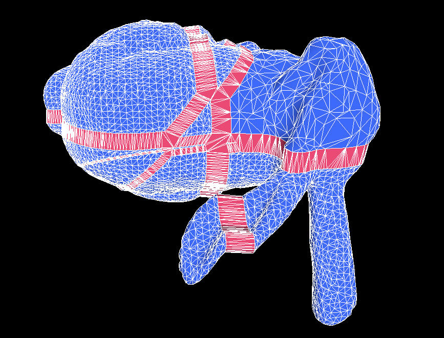
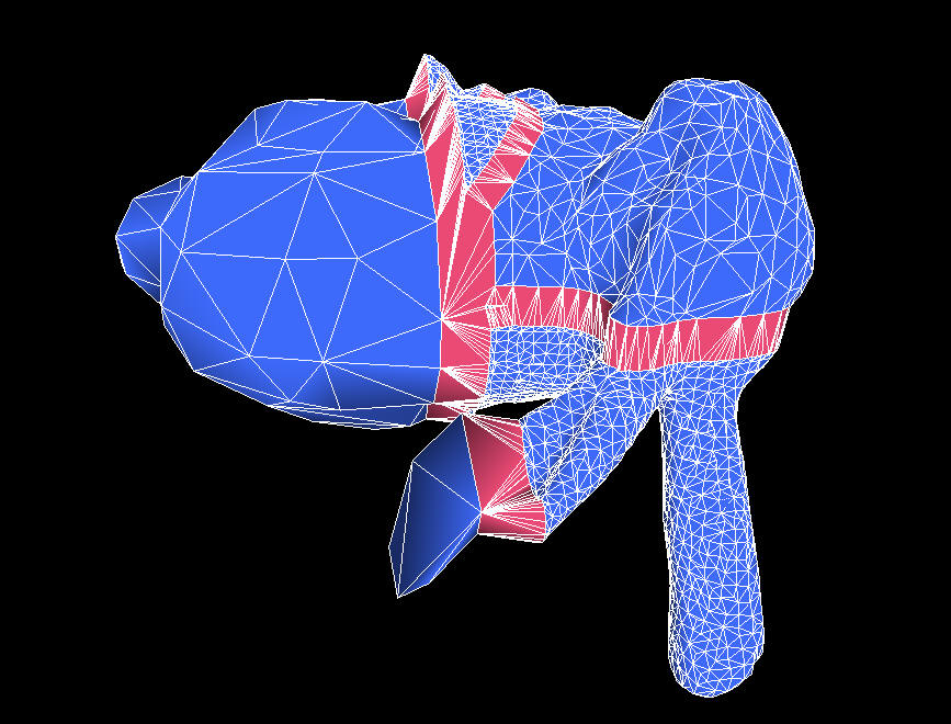
The second system in the sample code is a new version of the bunny chopping
program, modified now to use an arbitrary number of splitting planes. This
program serves as an illustration of the BSP-style cutting planes I am talking
about, and it serves to verify that the mesh chunking and pinhole-filling
schemes work properly. You can see the results in Figure 3.
Next month we'll look at LOD metrics, discuss methods of choosing splitting
planes, and generally finish things up.
 |
 |
 |
 |
| Figure 3 3a (upper left): The Stanford Bunny, chopped into arbitrary chunks by four different splitting planes. The original mesh contained 16000 triangles, but the portion in the upper-right has been reduced by one level of detail. The seam-filling triangles have been drawn in red, and the pieces of the bunny have been pulled apart so that you can see the seams. 3b (upper right): The same geometry as 3a, but rendered more like it would be in an actual game, without the pieces pulled apart. 3c (lower left): Like 3a, but now we have reduced the left half of the mesh by three levels of detail. Note that the seams are still properly filled. 3d (lower right): Like 3c, but without the pieces pulled apart. |
|